Activated Carbon Adsorption Process
1.1 Introduction to activated carbon adsorption process
Activated carbon adsorption column is the best purification equipment used for treating organic waste gas and odor. Activated carbon adsorption is an effective way to remove odor from water, natural and synthetic dissolved organic matters and micro-pollutants. The adsorption equipment is used for purification of high concentration organic waste gas and paint waste gas. It adsorbs organic waste gas molecules through the high strength adsorption force of activated carbon itself and the action of blowers, and can adsorb waste gas of organic solvent effectively. In actual installation and application, an activated carbon adsorption column that has been improved in the design and manufacturing and has simple blanking form, better surface flatness, higher structural strength and stronger adsorption capacity is introduced based on the production experience of similar products at home and abroad. The design of our activated carbon adsorption plant is improved based on the adsorption principle of activated carbon and the features of similar adsorption products. The plant can treat a large volume of waste gas, and uses pneumatic valves. It can be operated and managed simply and safely.
Adsorption process: due to the existence of unbalanced and unsaturated molecular attraction or chemical bond force on a solid surface, the solid surface can attract gas molecules when it is in contact with gas, so that gas molecules are concentrated and kept on the solid surface, this phenomenon is called adsorption. By the adsorption capacity of the solid surface, waste gas is in contact with porous solid substances on the large surface, then pollutants in the waste gas are adsorbed on the solid surface, so that the pollutants are separated from the gas mixture, achieving the purpose of purification.
(2) Scope of application
Production of electronic elements, battery (accumulator) production, pickling workshops, laboratory ventilation, metallurgy, chemical plants, pharmaceutical factories, painting workshops, food and brewing, furniture manufacturing and so on.
2.Large volume and low concentration waste gas or workshops of organic solvent to be recycled in intermittent operation.
(3) Structure and features of the plant
The plant is mainly made up of an adsorption tank, a condenser, a separator, an aerator and a main exhaust blower, and equipped with inlet and outlet valves, a carbon layer overtemperature alarm and automatic cooling device, and an electric control cabinet.
The purification plant can be equipped with one tank or two tanks according to the production process. One tank is generally equipped in intermittent production; and two adsorption tanks are equipped in continuous production, one tank is used for adsorption, and the other tank is used for desorption, and the two tanks can be also used at the same time. Manual valves that can be operated simply and reliably are arranged at the air inlet and outlet of the plant. The plant uses low pressure steam as the desorption medium, and a steam filter can be equipped for desorption of solvent with high boiling point to raise the steam temperature. When the two tanks are used for adsorption and regular desorption at the same time, the volume of gas treated is nearly doubled, reducing the investment and floor space in intermittent production.
1.2 Flow chart of activated carbon adsorption process
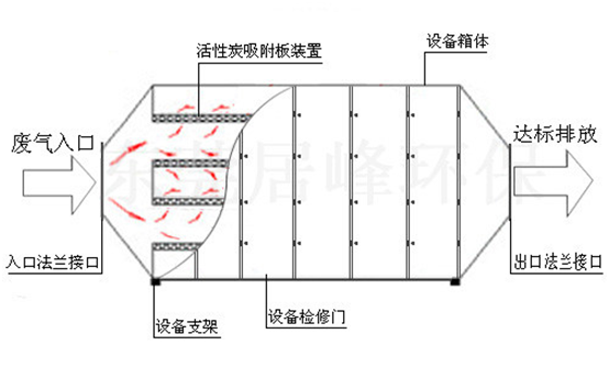
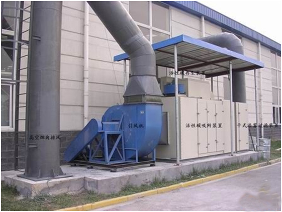
1.3 Engineering example of activated carbon adsorption process
II.Chemical Spray Absorption Process
Introduction to chemical spray absorption process
Waste gas is in cross-flow contact with absorption liquid (e.g., diesel, kerosene, water, acid-alkali liquid, plant liquid and other media), so that the waste gas is in full contact with the absorbent, as a result, pollutants in the waste gas are dissolved in the absorption liquid or react chemically with the absorption liquid (acid-alkali neutralizing reaction) according to the “like dissolves like” principle so as to remove the pollutants from the waste gas.
Structure: the equipment is divided into single column and double column. It is made up of a storage tank, a column, an air inlet section, a spray layer, a packing layer, a cyclone demisting layer, a ventilation conical cap and a manhole.
Features of the equipment
Novel structure: the conventional gas-liquid cross-flow bubbling contact form is changed;
Large volume of gas treated: the volume is 50% larger than that of sieve trays and valve trays;
Lower pressure: the pressure is 16% lower than that of conventional absorption columns;
High purification efficiency: the purification efficiency of conventional absorption columns is about 70%, while the absorption efficiency of new vertical sieve tray is higher than 85%;
High flexibility: the number of spray column layers can be increased or decreased according to different sources of waste gas.
The equipment is applicable to odor treatment, organic waste gas treatment, acid and alkaline gases, and incineration of tail gas.
2.2 Flow chart of chemical spray absorption process
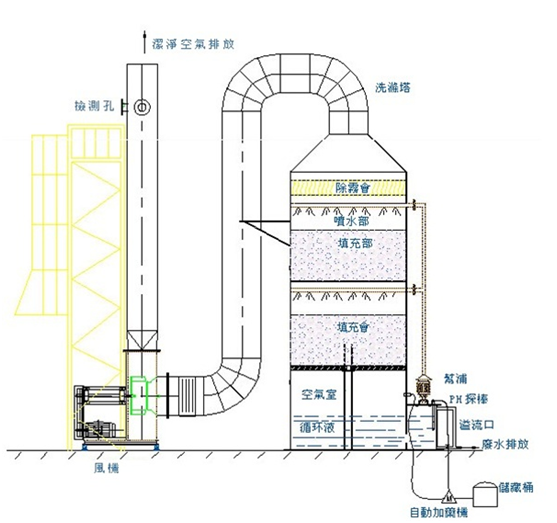
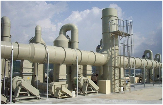
2.3 Engineering example of chemical spray absorption process

III.Low Temperature Plasma Technology
Introduction to low temperature plasma technology
Under the action of applied electric field, a large number of live electrons discharged by plasma in the media attack pollutant molecules to ionize, dissociate and excite these molecules, triggering a series of complicated physical and chemical reactions, so that complicated macromolecular pollutants are transformed into simple micromolecular safe substances, or toxic and harmful substances are transformed into non-toxic and harmless or less toxic and less harmful substances, so that the pollutants can be degraded and removed.
Low temperature plasma reaction process
Electric field + electrons → high energy electrons
High energy electrons (or atoms) → (excited atoms, excited groups, free radicals) active groups
Active groups + molecules (atoms) → product + heat
Active groups + active groups → product + heat
Summary of product performance
Effective deodorant: the product can effectively remove such main pollutants as volatile organic compounds (VOC), inorganic matters, hydrogen sulfide, ammonia and thiols, as well as all kinds of odor. Its deodorization efficiency, up to 99.9% or more, is much higher than that in emission standards for odor pollutants published inChina.
II. No need for additional substance: the corresponding exhaust duct and exhaust power are exclusively required for deodorization, decomposition and purification of odor gases through the equipment without adding any substance for chemical reaction.
III.Strong adaptability: The equipment is adaptable to deodorization and purification of a large volume of different high concentration odor gases. It can work for 24 hours every day stably and reliably.
Low operation cost: The equipment works without mechanical action and noise. Special management and routine maintenance are not required, but only regular inspection is required. The equipment has low energy consumption (the power consumption is only about 0.1kw for every 1000m3/h), and the wind resistance is very low (<30pa), saving a lot of exhaust power consumption.
V. No need for pretreatment: Special pretreatment such as heating and humidification is not required for odor gases. The equipment can work properly at an ambient temperature of -30℃ to 95℃, and humidity of 40% to 98%.
VI.Small floor space and light weight of the equipment: The equipment is suitable for use in special conditions such as compact layout and small site. The floor space of the equipment is smaller than 1m2/10000m3/h gas.
VII.High quality materials: high fireproof and anti-corrosion performance, stable performance and long service life
(3)The equipment is applicable to odor treatment and organic waste gas treatment.
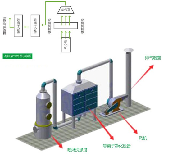
Flow chart of low temperature plasma technology
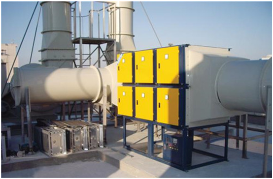
Engineering example of low temperature plasma technology
IV. Photocatalytic Oxidation Process
Introduction to photocatalytic oxidation process
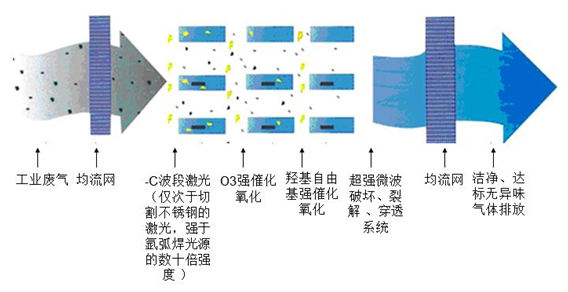
When the molecules of pollutants are radiated by high-intensity nano ultraviolet light generated by photooxidation and optical microwave, all molecular chains of organic waste gas are completely broken down, cracking and changing the structures of the pollutants, so that macromolecular pollutants are cracked and broken down into micromolecular harmless substances such as water and carbon dioxide.
Organic matters are transformed into water and carbon dioxide by breaking down macromolecular chains into micromolecular chains, oxidation of ozone and hydroxyl radical, and catalytic oxidation of catalyst so as to remove the organic matters.
Technical features
1.Low temperature in-depth reaction
Organic pollutants in air, water and soil can be completely oxidized into non-toxic and harmless substances at normal temperature by photocatalytic oxidation. However, pollutants can be destroyed only at very high temperature by conventional high temperature incineration technology. High temperature (hundreds of degrees) is also required in conventional catalytic oxidation methods.
Thorough purification
Organic pollutants in air can be directly oxidized into non-toxic and harmless substances completely without any secondary pollution by photocatalytic oxidation. However, pollutants are not broken down by the activated carbon adsorption process widely applied at present, but only the sources of pollution are transferred.
3.Green energy
Photocatalysis can use sunlight as energy to activate the photocatalyst, driving the oxidation-reduction reaction, and the photocatalyst is not consumed during the reaction. In terms of energy, this feature makes the photocatalytic technology more attractive.
4.High oxidability
According to many studies, semiconductor photocatalysis has the feature of high oxidability, and can effectively break down some organic matters such as trichloromethane, carbon tetrachloride and hexachlorobenzene which are hardly oxidized by ozone. As a result, semiconductor photocatalysis is of special significance to refractory organic matters. Hydroxyl radical (OH) is an effective oxidant for photocatalysis, and the oxidability of OH oxidation is higher than common ozone, hydrogen peroxide, potassium permanganate and hypochlorous acid.
5.Broad spectrum
Photocatalysis is effective against a variety of organic matters from hydrocarbons to carboxylic acids, and the nine categories of 14 pollutants released by EPA have been proven to be treated by photocatalysis. In addition, photocatalysis has good effect on removal of atomic organic matters such as halogenated hydrocarbons, dyes, nitrogen-containing organic matters and organophosphorus insecticide, and can completely purify these pollutants through continuous reaction in general.
6.Long shelf life
In theory, the life of catalyst is infinite.
(3)Photocatalysis is applicable to odor treatment and organic waste gas treatment.
4.2 Flow chart of photocatalytic oxidation process
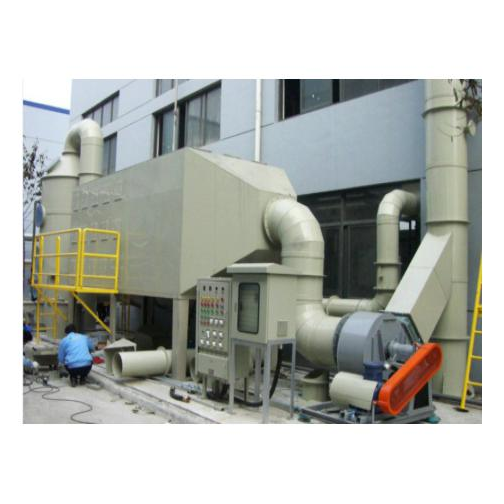
4.3 Engineering example of photocatalytic oxidation process
V.Biological Deodorization Process
Introduction to biological deodorization process
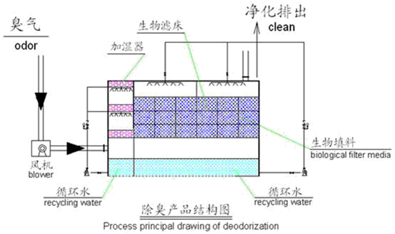
Under suitable environmental conditions, microorganisms continue to absorb nutrients, and carry out metabolic activities in their own metabolic way. Biological treatment of waste gas is to transform harmful substances in waste gas into simple inorganic matters such as carbon dioxide, water and cellular substances based on the feature that nutrients are required in the metabolic process of microorganisms.
Treatment process of biofiltration process
1.Pollutants in waste gas are in contact with water and then dissolved in water (diffused from the gas film into the liquid film);
2.The pollutants dissolved in the liquid film are further diffused into the biofilm under the effect of concentration difference, then captured and absorbed by the microorganisms therein;
3.The microorganisms transform pollutants into biomass, metabolic by-products or CO2, water and so on;
4.The biochemical reaction product CO2 is desorbed from the surface of the biofilm and reversely diffused into the gas phase, and H2O is kept in the biofilm.
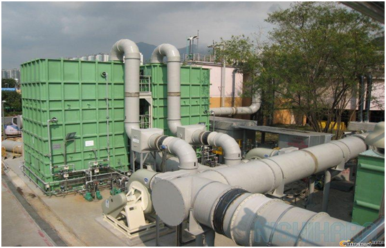
(3)Biofiltration process is applicable to odor treatment and organic waste gas treatment.
5.2 Flow chart of biological deodorization process
5.3 Engineering example of biological deodorization process
VI.Regenerative Thermal Waste Gas Treatment Process Using Molecular Sieve Wheel
6.1 Introduction to regenerative thermal waste gas treatment process using molecular sieve wheel
Introduction to the process
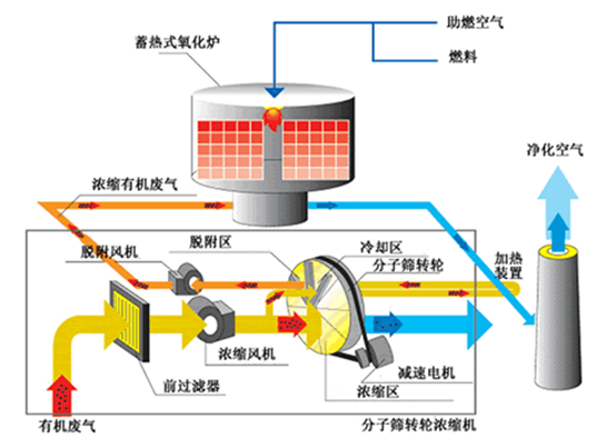
1.The molecular sieve wheel concentrator concentrates low concentration and large volume organic waste gas into high concentration gas by adsorption and desorption procedures of adsorption - desorption - concentration.
2.The plant is suitable for treating large volume and low concentration waste gas containing various organic components.
3.Through the rotation of the wheel, gas desorption and regeneration of the wheel can be completed on the wheel at the same time.
4.The organic waste gas entering the concentration wheel is directly discharged to the atmosphere after being adsorbed and purified by the adsorption zone of the wheel at room temperature.
5.Then organic substances enter the desorption zone with the rotation of the wheel, and the wheel adsorbing the organic substances is desorbed in the zone.
6.The organic matters adsorbed on the wheel are separated and desorbed, and then enter the subsequent treatment system for cycle treatment.
(2)The process is applicable to treatment of organic waste gas and petrochemical waste gas.
6.2 Flow chart of regenerative thermal waste gas treatment process using molecular sieve wheel
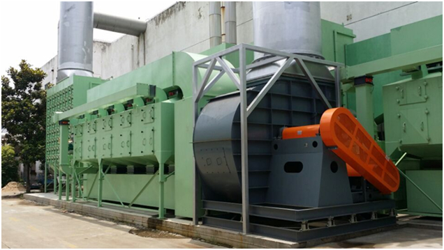
Engineering example of regenerative thermal waste gas treatment process using molecular sieve wheel


 Scan focuses on the site